I hope you find this Convert to Sheet Metal tool helpful. This command acted as a Shell command and removed the front face that was not included in any of the edge selections.

The original solid part is now a Sheet Metal part with sheet metal parameters complete with flat pattern. When all information is entered, click OK. The Convert Sheet Metal tool automatically selects the edges that will be ripped with the specified gap. These are the 4 edges on the part that will represent bends.

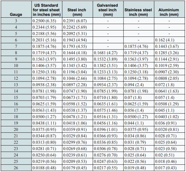
Once this information is entered , we pick the Fixed Face (which in this case is the bottom.) Next, we choose the Bend Edges. The first selection is the type and gauge of Sheet Metal that will be used for this solid part. It will all be done within the Convert to Sheet Metal command.Ĭlick on Convert to Sheet Metal. For this example, you don't need to use the RIP and Insert Bends tools separately.

For this example, I added an edge flange to 4 edges. You must be in the Generative Sheetmetal Design workbench. All radii in the solids need to maintain constant thickness. Convert old sheet metal parts for use in the Generative Sheet Metal Design workbench. Go to the Sheet Metal Feature and edit.Īllow all other sheet metals tool functionality. Create sheet metal parts from existing solid geometry. This part will now accept Sheet Metal Material Properties. A bend radius is entered along with a K-Factor, if desired. In this example, it's the bottom highlighted in green. On this example, I've picked 2 edges and inserted a GAP dimension. The RIP tool breaks a solid along a corner to make it suitable for adding bends. The Feature Manager shows the imported part. Click on the Convert to Sheet Metal icon in For this example, I set the unit system of the model to MMGS. This means there is a single monolithicįeature with no parametric data. During sheet metal part bending, the inside bending surface is compressed, whereas the outer surface is stretched. Mathematically k factor value is equal to the ratio of position of neutral axis and sheet thickness. Neither of these operations is necessary so select NO for each. K Factor in sheet metal bending is a constant used to calculate sheet metal flat length or Flat-pattern. Import, we are asked to do a Feature recognition and Import Diagnostics. Each example has a little different approach. Imported part and the second example will be converting a solid part. The Covert to Sheet Metal command combines Them to sheet metal with associated sheet metal properties. We create a familiar solid part, non-sheet metal bodies, and convert Using Publish / Copy geometry, you can use the original part to parametrically drive changes to the flat part.SolidWorks makes it easy to create sheet metal parts out of solid or imported parts. Of course, being that the surface is on one side of the part, you'll have to offset it the value of the K-factor to give you a better approximation of the developed length (if that is required.) "flatten quilt" tends to work on geometry that can't be flattened using Unbend or Flat Pattern. Then, you can try "flatten quilt" to flatten the surface and then "thicken" it. One of my favorite ways to convert difficult parts (for flattening) is to use Publish Geometry and copy surfaces into a new part. If the geometry is split into 2 parts, you'll have problems. Import parts into SOLIDWORKS, then use the rip feature to create thin cuts in sheet metal geometry between adjacent flanges. You can use driving surface or shell conversion to guarantee uniform thickness. It is possible to convert geometry to sheet metal and not have something that will flatten (or flatten easily).įor conversion to sheet metal, you just need contiguous geometry which is uniform thickness. It is important to make the distinction between 1) conversion to sheet metal 2) flattening a sheet metal part.


 0 kommentar(er)
